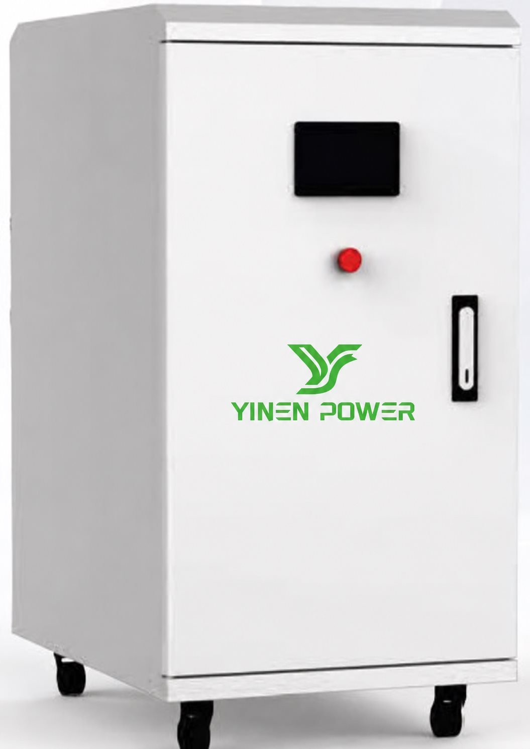
ESS GU 5 / 10 / 21 kWh
5.18–21.12 kWh192 / 384 VDC
Models: 5 / 10 / 21 kWh
Discharge current: 54 / 110 A
Cabinet height: 900–1850 mm

ESS GU SERIES
LiFePO4 battery cabinets for UPS backup applications, covering published ESS GU configurations from 5.18 kWh to 107.52 kWh.
CONFIGURE YOUR BACKUP
The four published ESS GU product groups below cover twelve capacity configurations. Confirm the load profile, UPS DC bus requirement, required autonomy and local installation conditions before ordering.
5.18–21.12 kWh192 / 384 VDC
Models: 5 / 10 / 21 kWh
Discharge current: 54 / 110 A
Cabinet height: 900–1850 mm
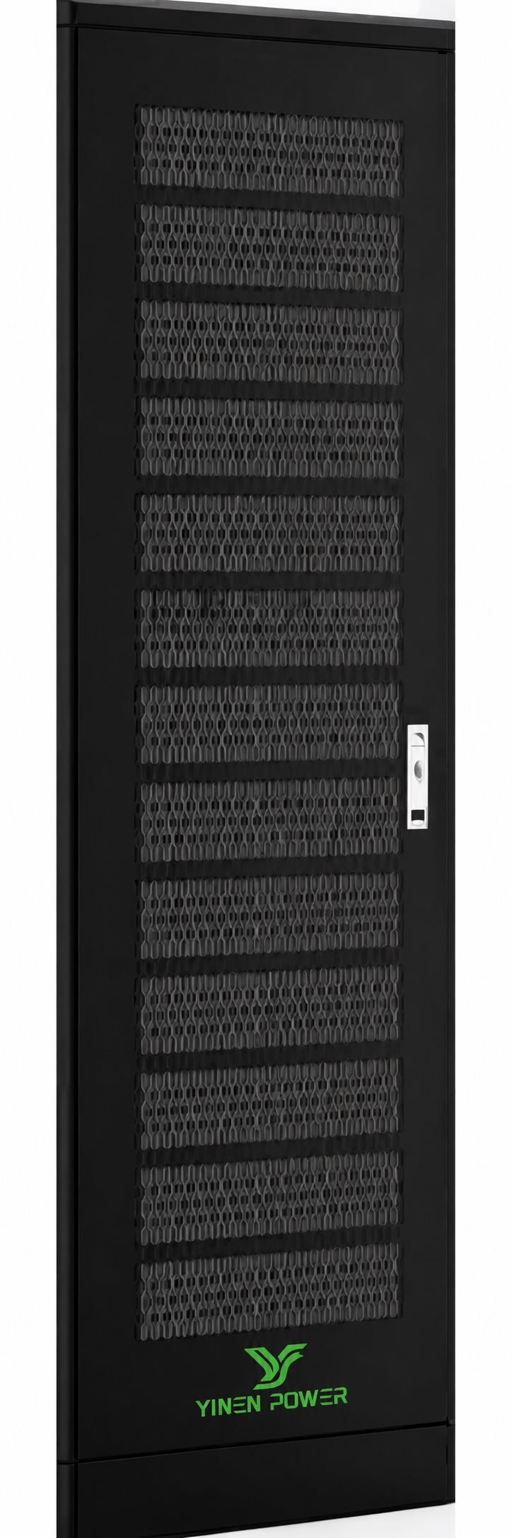
40.32–107.52 kWh192–512 VDC
Models: 40 / 54 / 80 / 108 kWh
Discharge current: 210 / 420 A
Air cooling: Published
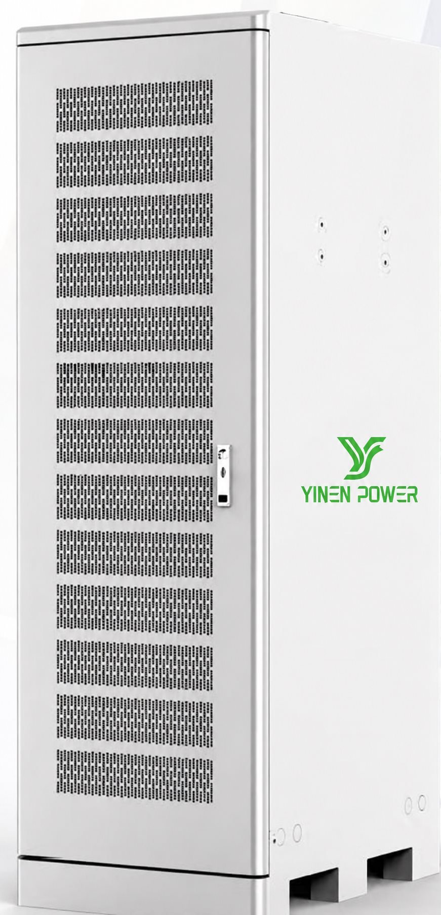
11.52–30.72 kWh192–512 VDC
Models: 11 / 23 / 30 kWh
Discharge current: 240 A
Cell capacity: 60 Ah
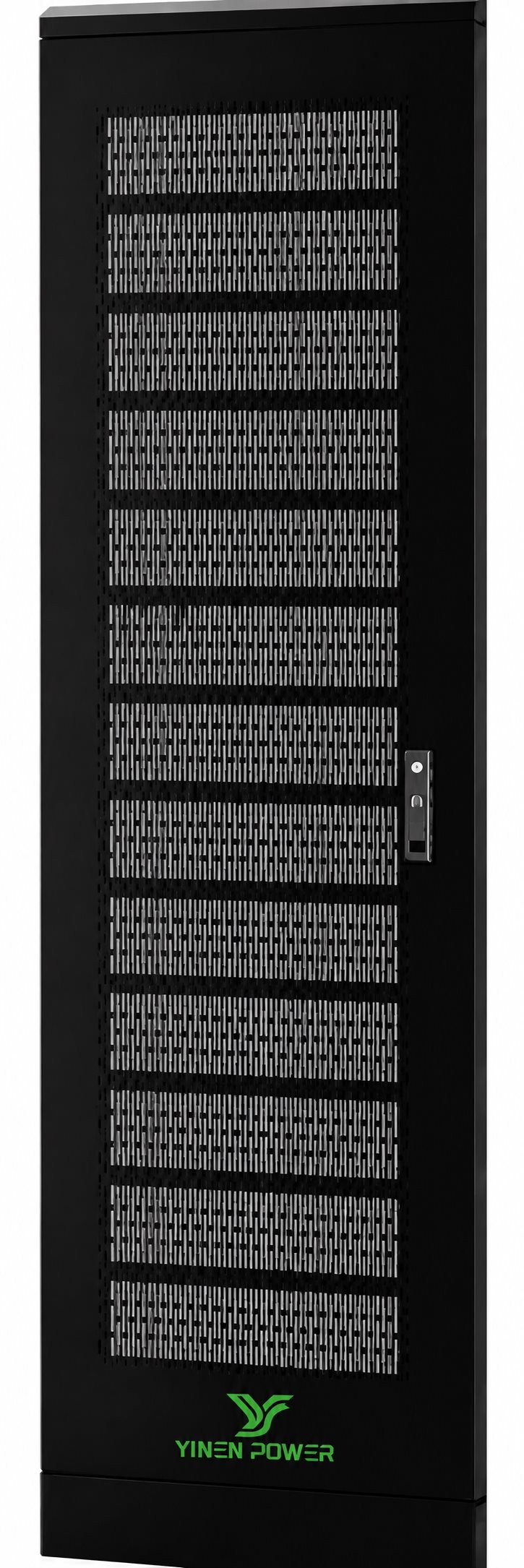
46.08 / 61.44 kWh192 / 256 VDC
Models: 46 / 61 kWh
Discharge current: 480 A
Cell capacity: 120 Ah
PRODUCT OVERVIEW
The ESS GU series uses published LiFePO4 battery configurations for UPS backup projects. The factory brochure describes high-current discharge options, wide DC-voltage adaptation and CAN/RS485 communication for coordinated battery monitoring.
Final selection must be based on the UPS model, DC bus voltage, continuous and peak load, required backup time, available installation space, transport route and applicable local requirements.
Battery chemistry: LiFePO4
Communication: CAN / RS485
Ingress protection: IP20
Charge / discharge: 0–55 °C / −20–55 °C
Humidity: 0–95% non-condensing
TECHNICAL DATA
| Model | Energy | Nominal voltage | Voltage range | Max. discharge | Dimensions (L × W × H) |
|---|---|---|---|---|---|
| ESS GU 5 kWh | 5.18 kWh | 192 VDC | 174–218 VDC | 54 A | 600 × 700 × 900 mm |
| ESS GU 10 kWh | 10.37 kWh | 384 VDC | 348–432 VDC | 54 A | 600 × 700 × 1500 mm |
| ESS GU 21 kWh | 21.12 kWh | 384 VDC | 348–432 VDC | 110 A | 700 × 700 × 1850 mm |
| ESS GU 40 kWh | 40.32 kWh | 384 VDC | 348–432 VDC | 210 A | 1100 × 700 × 2200 mm |
| ESS GU 54 kWh | 53.76 kWh | 512 VDC | 464–576 VDC | 210 A | 800 × 1210 × 1550 mm |
| ESS GU 80 kWh | 80.64 kWh | 192 VDC | 174–216 VDC | 420 A | 1100 × 700 × 2200 mm |
| ESS GU 108 kWh | 107.52 kWh | 256 VDC | 232–288 VDC | 420 A | 1100 × 1210 × 1550 mm |
| ESS GU 11 / 23 / 30 kWh | 11.52 / 23.04 / 30.72 kWh | 192 / 384 / 512 VDC | 174–218 / 348–432 / 464–576 VDC | 240 A | 700 × 700 × 1250 / 2200 mm; 700 × 1210 × 1550 mm |
| ESS GU 46 / 61 kWh | 46.08 / 61.44 kWh | 192 / 256 VDC | 174–218 / 232–288 VDC | 480 A | 1150 × 700 × 2200 mm; 1150 × 1210 × 1550 mm |
Specifications are transcribed from the supplied factory brochure and remain subject to the latest factory documentation.
APPLICATION SCENARIOS
Define the protected loads, start-up current and required autonomy for data rooms, telecom facilities, control rooms or other essential equipment.
Check the UPS DC bus window, communication requirements, protection coordination and cabinet footprint before replacing a legacy battery system.
Review both steady-state demand and peak discharge requirements to determine whether the standard or high-rate configuration is suitable.
Confirm installation access, maintenance clearance, transport constraints, site temperature and future expansion needs in the project design.
COMMON QUESTIONS
Share the UPS model, DC voltage window, load profile, peak demand, target backup time, installation location and destination country. The final configuration must be checked against the latest factory documentation.
The supplied brochure lists CAN and RS485 communication. Confirm the exact UPS protocol and battery-management compatibility for the intended project.
No. Published nominal voltages and working ranges differ by model. Use the specification table to shortlist compatible models, then obtain final factory confirmation.
Please provide your UPS model, required energy, DC bus voltage, load data, backup time, installation location, destination country and quantity.
High-rate discharge selection should be based on the UPS load profile, peak current, required autonomy and battery-duty cycle. Provide these values for a model-specific engineering review instead of selecting by energy capacity alone.
Plan adequate cabinet clearance, ventilation, maintenance access, a suitable transport route and a dry indoor environment. The brochure states IP20 protection, so the final installation must follow the applicable site and electrical requirements.
Expansion feasibility depends on the UPS DC bus, the selected ESS GU model, BMS communication, protection design, battery consistency and the available physical space. Confirm the expansion plan before the initial configuration is ordered.
PROJECT CONFIGURATION
Share your UPS model, DC bus voltage, energy target, backup time, location and quantity for a practical configuration review.
