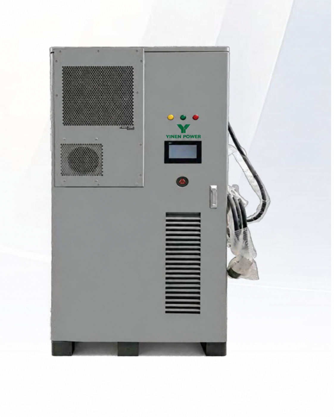
PEC-50PCS-60EV-112KWH
112 kWhLiFePO4IP54
PV input range: 200–800 V
Battery voltage range: 313.6–403.2 VDC
AC rated power: 50 kW
DC charging power: 40 / 60 kW

PEC SERIES
Integrated photovoltaic, battery storage and EV charging systems for commercial sites, fleet charging and distributed-energy projects.
CONFIGURE YOUR PROJECT
Select the published PEC configuration that matches your storage target, PV input plan, EV charging requirement and installation conditions.
112 kWhLiFePO4IP54
PV input range: 200–800 V
Battery voltage range: 313.6–403.2 VDC
AC rated power: 50 kW
DC charging power: 40 / 60 kW
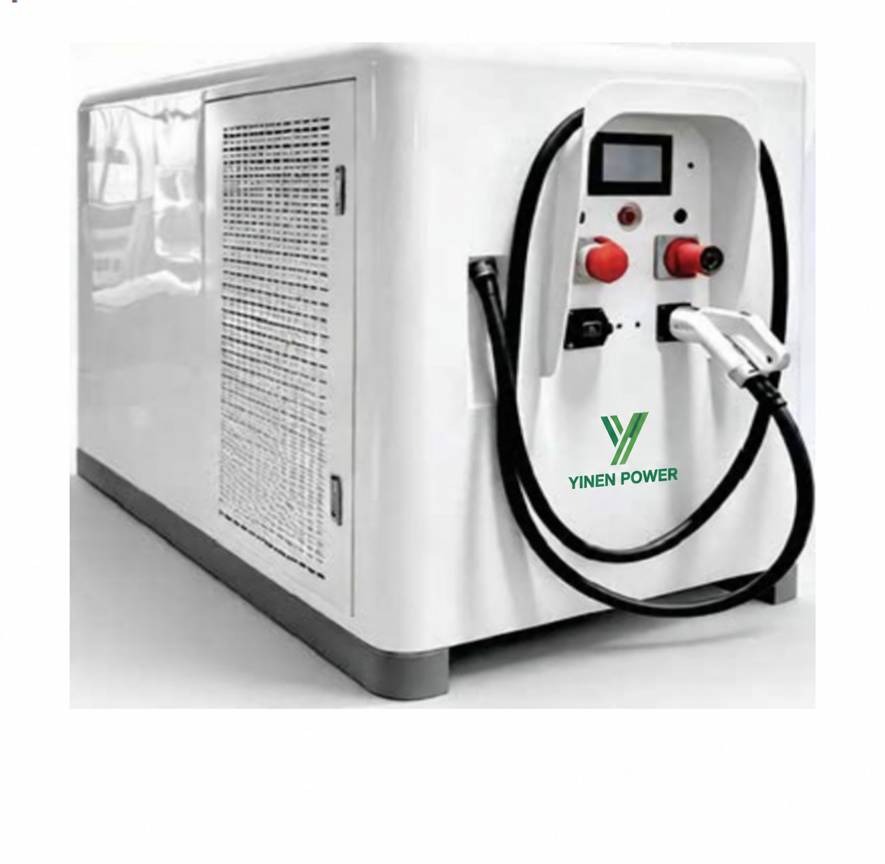
208 kWhLiFePO4IP54
PV input range: 200–800 V
Battery voltage range: 582.4–748.8 VDC
AC rated power: 50 kW
DC charging power: 120 kW
PRODUCT OVERVIEW
The PEC series combines PV conversion, energy storage, AC power output and DC charging to support coordinated on-site energy use. Use the published data for initial project planning only; final engineering must match the current factory documentation and local electrical requirements.
Both systems are designed for applications where solar self-consumption, charging infrastructure and stored-energy availability need to be evaluated together.
Battery chemistry: LiFePO4
PV MPPT trackers: 2
PV start-up voltage: 250 V
Rated grid voltage: 400 / 230 V
Communication: RS485 / CAN / Wi-Fi
Protection class: IP54
TECHNICAL DATA
| Parameter | PEC-50PCS-60EV-112KWH | PEC-50PCS-120EV-208KWH |
|---|---|---|
| Battery type | LiFePO4 | LiFePO4 |
| Battery energy | 112 kWh | 208 kWh |
| Battery voltage range | 313.6–403.2 VDC | 582.4–748.8 VDC |
| Max. battery / recharge current | 150 A | 157 A |
| PV input voltage range | 200–800 V | 200–800 V |
| PV max. voltage | 850 V | 850 V |
| PV max. input power | 38.4 kW + 38.4 kW | 38.4 kW + 38.4 kW |
| AC rated power | 50 kW | 50 kW |
| DC charging output | 40 / 60 kW; 200–1000 V | 120 kW; 200–1000 V |
| DC charging max. current | 100 / 200 A | 250 A |
| Cooling method | Intelligent air cooling | Liquid cooling + intelligent air cooling |
| Protection grade | IP54 | IP54 |
Specifications are transcribed from the supplied factory brochure and remain subject to the latest factory documentation.
APPLICATION SCENARIOS
Coordinate DC charging demand with PV generation and stored energy to support customer, employee or fleet-charging projects.
Assess daily load, peak demand, grid capacity and operational priorities for facilities seeking on-site energy coordination.
Use the published PV window, storage capacity and AC parameters as inputs for a site-specific PV and energy-management design.
Define critical loads, backup expectations, charger duty cycles and future expansion needs before confirming the final configuration.
COMMON QUESTIONS
Share the expected charging power, daily charging volume, PV plan, site load profile, grid voltage, installation location and required storage capacity for a practical configuration review.
The published configurations include DC charging outputs. Confirm connector standards, charging protocol, output requirement and local compliance requirements for the target project.
The series is designed as an integrated PV, storage and charging solution. The final control logic, grid connection and protection design must be reviewed for the specific site.
Review the electrical connection, installation space, ventilation, transport route, maintenance access, climate, communication setup and applicable local requirements before ordering.
No. The values are transcribed from the supplied brochure. Confirm the latest factory documentation and project-specific configuration before placing an order.
PROJECT CONFIGURATION
Share your PV plan, charging requirement, site load, installation location, destination country and quantity for a practical configuration review.
